The Hermes-Lite Project
The Hermes-Lite project aims to design and market a software defined radio transceiver
that directly samples the antenna
with an analog to digital converter, is completely controlled by Ethernet, and costs about USD 200.
It is contained on a single 10x10 cm PCB. The standard enclosure is 10x15 cm and the extra space is meant for filters,
transverters and other add-on boards. The Version 2 hardware includes a 5 watt push pull MOSFET amp as well as a 40 mW low power output.
Since the FPGA and the digital up/down conversion is on-board, a sound card is not used for radio samples, and is only used
for the microphone and for playing radio sound.
Filter Board by James Ahlstrom, N2ADR
NOTE: Assembled filter boards and assembled Hermes Lite 2 boards are currently (October 2020)
available from Makerfabs.com.
Search for "Hermes Lite 2".
NOTE: A newer version of this board is available as part of the Hermes-Lite2 project.
See github .
The Hermes-Lite 2 is ready to use at 40 mW output or at 5 watts output as an exciter for a subsequent RF amplifier. But to use the 5 watt amp
as a complete QRP rig, it needs transmit low pass filters. I designed a 5x10 cm filter board that clips to the main board
and fits into the standard enclosure. It has transmit low pass filters for 160 to 10 meters, and a 3 MHz high pass filter for receive.
The filter board is automatically controlled by the Hermes-Lite main board through an I2C interface. Version E4 was released on March 29, 2018.
Here is the schematic of the filter board, the bill of materials and
the KiCad design files and gerbers. All the parts are available from mouser.com.
Refer to the schematic and the bill of materials for parts details. If a part is marked "DNI" it means do not install.
Thanks to Pascal, there is a Mouser saved cart.
Check for back ordered items, and perhaps add to the quantities in case some SMDs go flying. See parts substitutions below.
Filter Board Consruction
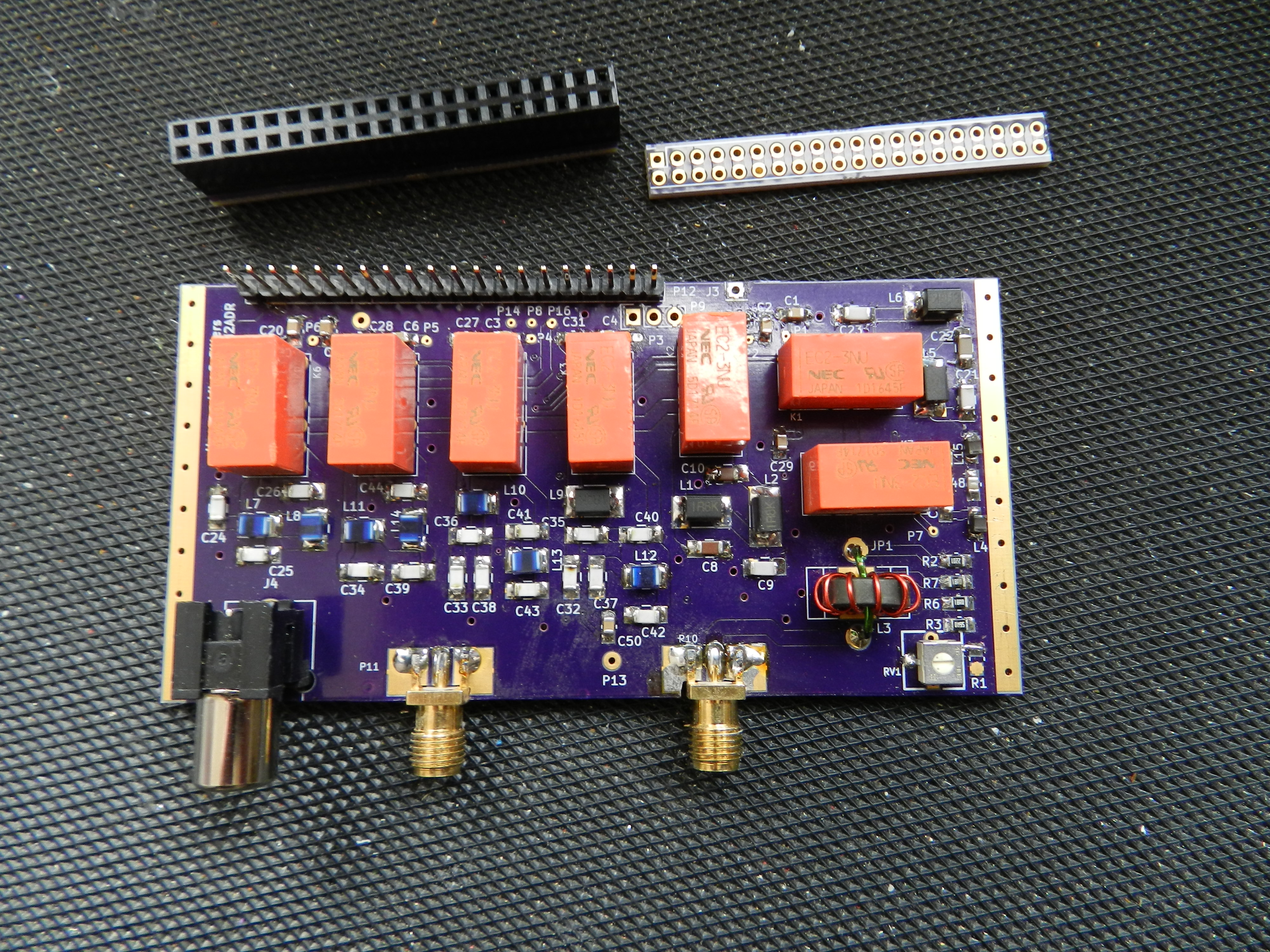
Here is a photo of the filter board. The 2x20 pin header has opposite pins connected together with the small PCB shown.
The design files for this PCB are here, but you could just solder opposite pins together.
The 2x20 header then plugs into two 1x20 pin headers on the Hermes-Lite and filter board to connect them together.
Or you could just wire the two boards together with bare wire jumpers if you don't need to separate them.
Take a close look at the SMA connectors. Since we are using the square SMAs, you must file a small notch in the board
so the front of the SMA is flush with the edge of the PCB. Do this as the first step before you populate the board.
Or you could use a round SMA that fits in a hole in the panel, and then this is not necessary. The trim pot shown in the
lower right corner is no longer used.
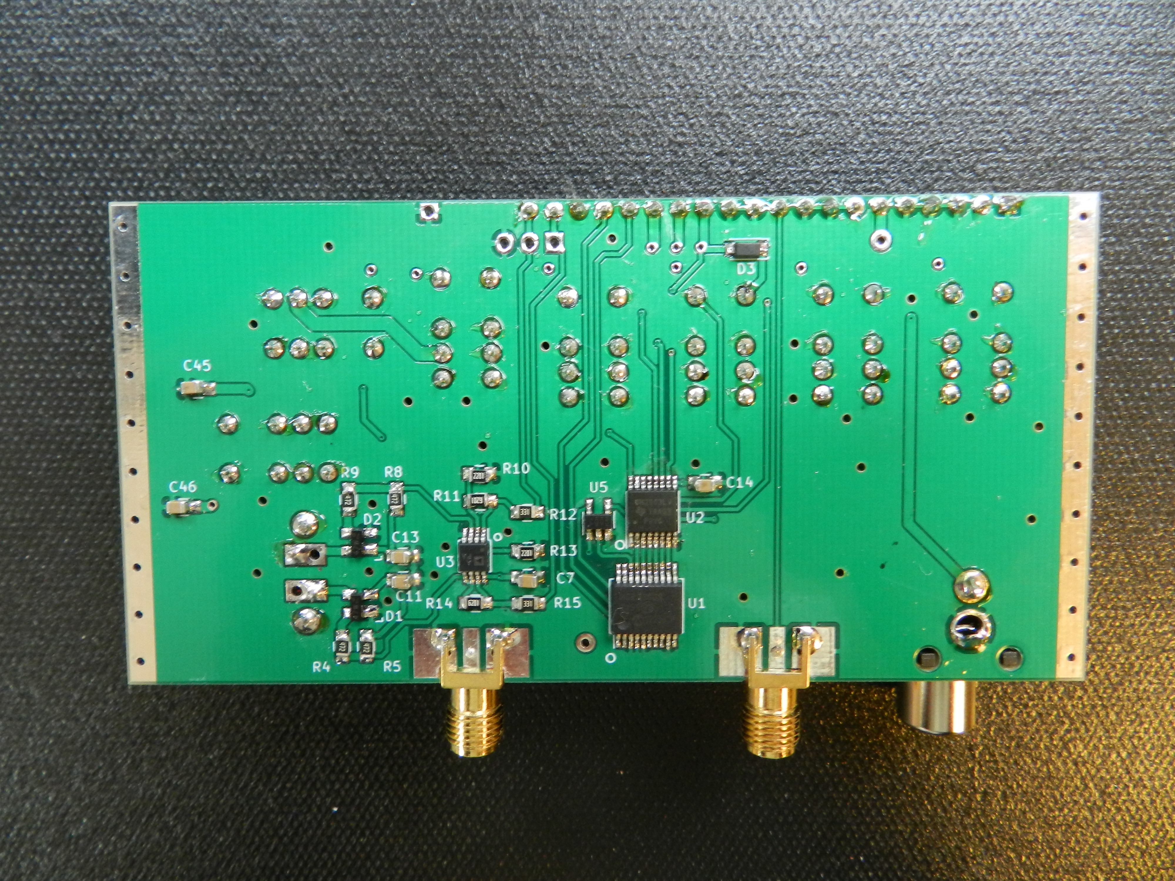
This photo shows the back of the filter board.
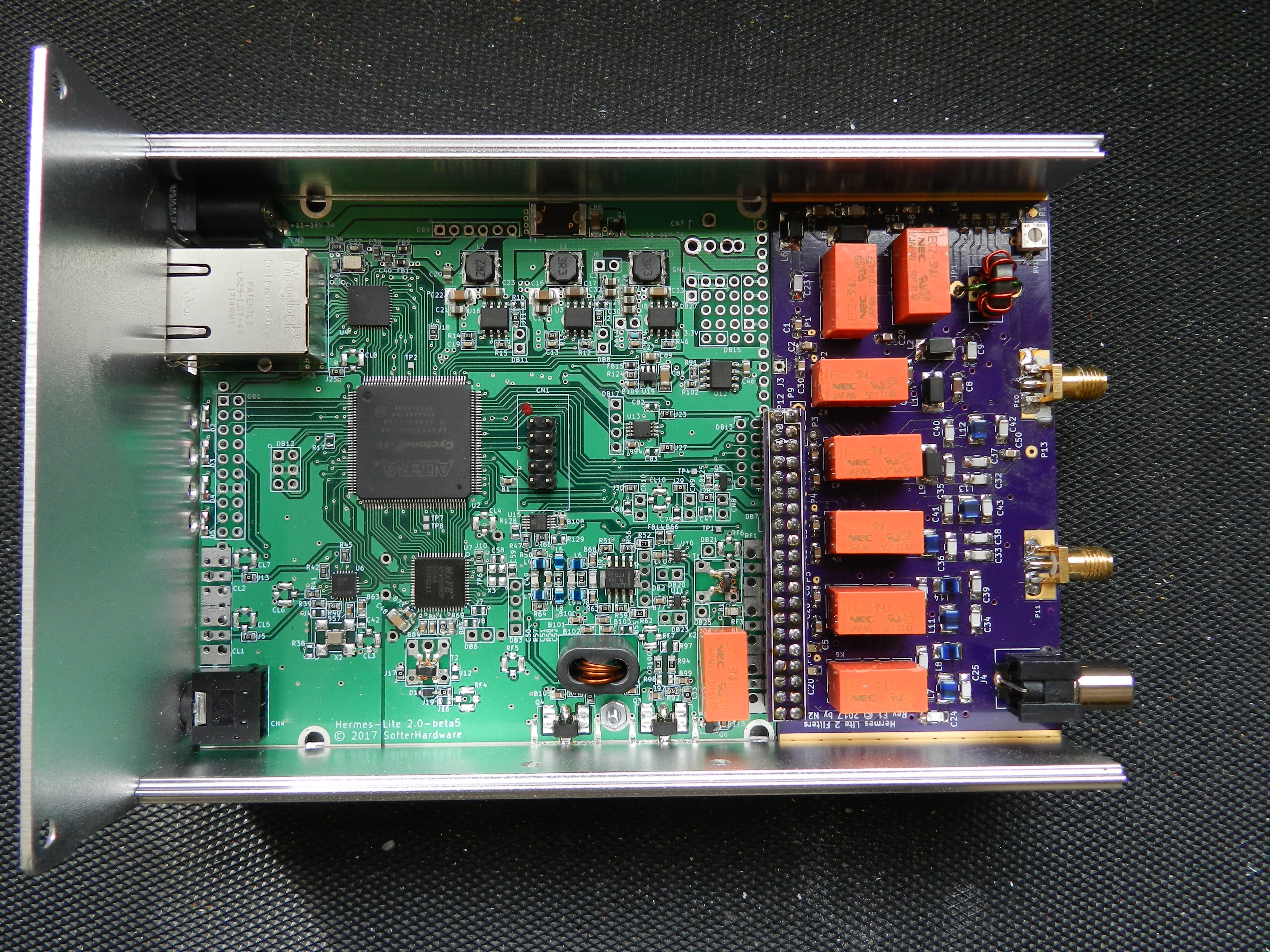
This photo shows the filter board and Hermes-Lite installed in the standard enclosure.
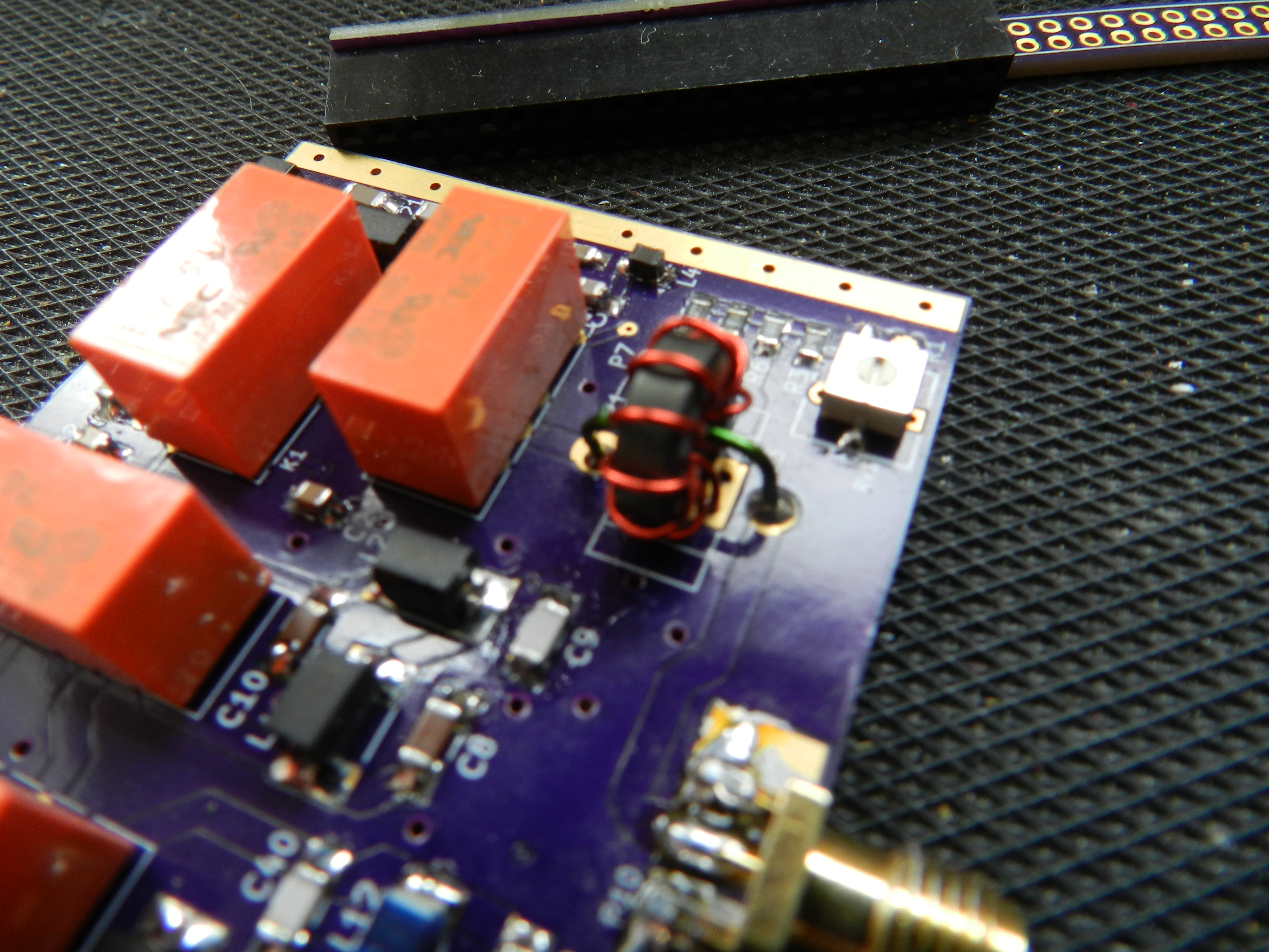
The power sensor requires a toroid transformer with ten turns and one turn. The next two photos show the transformer mounted on the board.

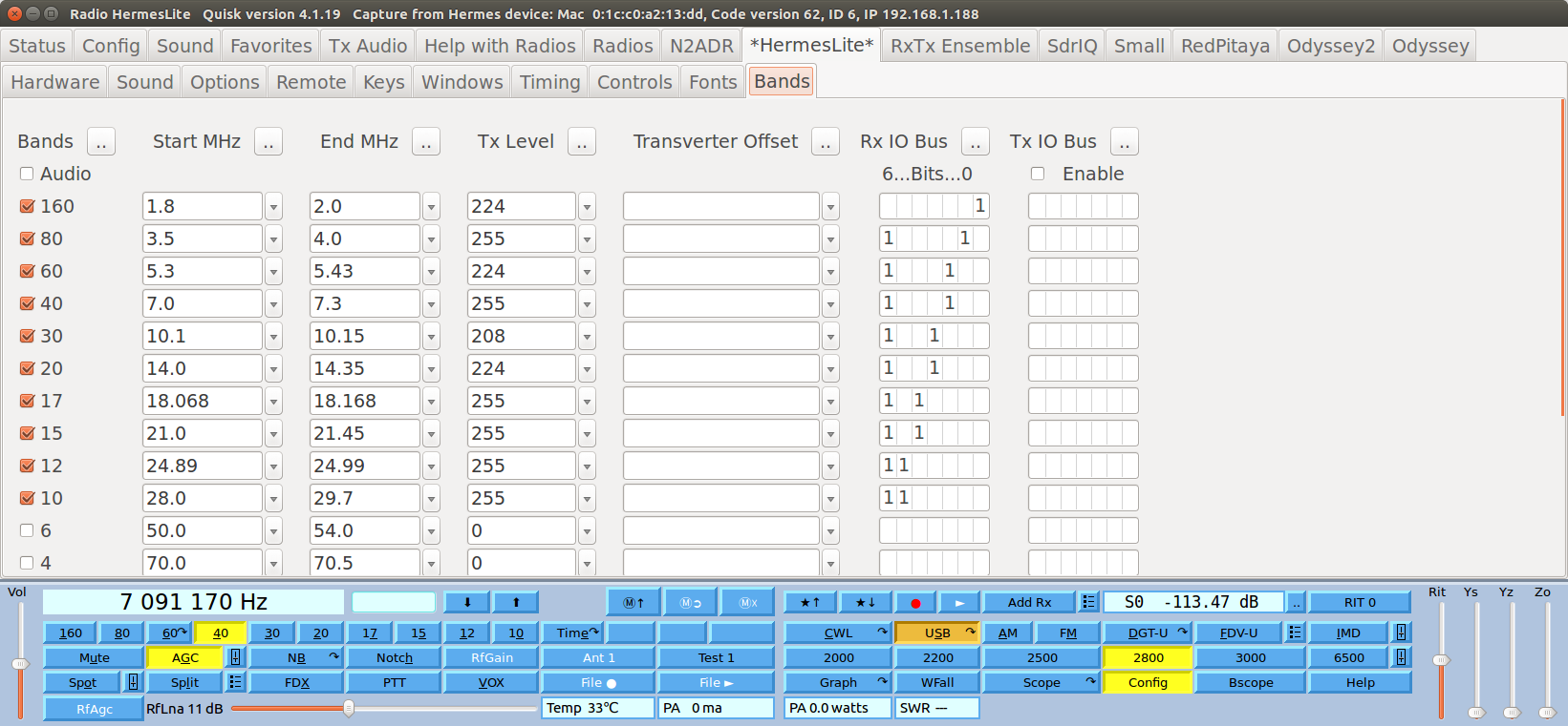
This is a screen shot of the Quisk Bands screen. The "Tx Level" setting lowers the transmit power to five watts on each band
to avoid driving the power amp too hard. Check the power output with a 50 ohm load to check the settings. The HL2 only has 16 power settings
even though the "Tx Level" can be adjusted from 0 to 255. The available settings are multiples of 16: 0, 16, 32, ..., 208, 224, 240.
Other settings are rounded down to these values. Each setting changes the power output by 0.5 dB.
The "IO Bus" controls a seven bit number sent to the filter board using an I2C interface. Each bit controls one of the seven relays
on the filter board. Bits are numbered 6 to 0 from left to right. Bit 6 controls a 3 MHz high pass filter to reject strong
AM broadcast band interference on receive. The high pass filter should be used on all bands except 160 meters. The other bits control low pass transmit filters.
Note that the transmit filter settings are not necessary, and only the receive filter settings are used. When multiple receivers are in
use, the receive filter for the highest band is used. But when transmitting, the filter for the transmit band is used
and the high pass filter is switched out by the hardware.
| Bit |
LPF Band |
| 0 |
160 meters |
| 1 |
80 |
| 2 |
60, 40 |
| 3 |
30, 20 |
| 4 |
17, 15 |
| 5 |
12, 10 |
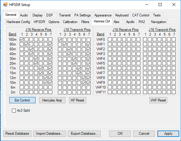
This is a screen shot of the PowerSDR Hermes filter settings.
Substitute Parts
The integrated circuits for the I2C interface, the high pass filter, the relays and the SWR bridge all use readily available components.
But you may need to find substitutes for the capacitors and inductors in the low pass filters. The specified capacitors are 630
volt NP0 (or C0G) in US 1206 (3216 metric).
I used these because I had them available and I knew they had a high Q and good current capacity. Unfortunately, the manufacturers
do not specify the Q or current. At 5 watts and 50 ohms, the peak voltage is 22 volts and the peak current is 0.45 amps.
But the impedance is not 50 ohms,
and we need to allow for open, short and arbitrary antenna impedance. You can try substituting 100 or 200 volt capacitors
provided they are the same package (1206), and are NP0 or C0G dielectric. Test by checking for heating.
The inductors are more of a problem. The manufacturers specify the Q but not the RF current capacity. They do specify a DC
current, but that is the current at which the inductance starts to decrease.
For the low pass filters, the inductors from 220n to 680n are wirewound on non-magnetic cores. You can try to substitute
other inductors on non-magnetic cores with the same or better DC current capacity. Inductors of one microhenry and up use ferrite cores,
and the characteristics of ferrite at RF can vary. You can try to substitute these, but you will have to test whether
they work at RF. A similar or larger DC current spec is a good start.