
James C. Ahlstrom
N2ADR
April, 2020
June, 2020
August, 2020
This paper considers several ways to connect a switch to a PC. Since PCs do not have IO ports and no longer come with serial or parallel ports, we will use a USB to serial port adapter. Later we will use an external microcontroller. This is motivated by the need to connect Morse code keys, paddles and electronic keyers to amateur radio equipment. In particular we want to connect a key to a PC and use it to send CW using a remote HermesLite2 which is connected to the PC by Ethernet. The HermesLite2 is a software defined radio transceiver that is optimized for low cost.
In case you are unfamiliar with amateur radio, a key is a switch, a paddle is two switches and a keyer is one switch that can send very fast switch changes. In all cases, the exact timing of switch closures must be maintained. At a fast but reasonable CW rate of 60 words per minute, the length of a "dit" is 20 milliseconds. We will present measurements of the switch speed possible on Windows and Linux PCs.
The serial port logic levels are -25 to -3 volts for False and 3 to 25 volts for True. But serial ports are often wired assuming that an open circuit or zero volts counts as False. Here is the pinout of the usual DB9. There are pins for transmitted data, received data and ground. There are two pins DTR and RTS that are set by the PC, and four pins that are read by the PC. We will be using DTR as a source of power, and the PC must set this pin. We will use CTS and DSR as switch inputs to the PC. There is no specification for how much power DTR can provide nor for how much current CTS needs. On my USB to serial adapter, unloaded DTR was 7.1 volts, connecting DTR to CTS through a 2K2 resistor dropped this to 5.9 volts. The CTS was drawing 0.8 ma. Connecting DTR to ground through a 2K2 resistor dropped the voltage to 5.7 volts.
Figure 1 is the schematic of the usual connections for a key or paddles. Note that DTR is being connected to CTS, DSR or both. Since none of these are at ground, it will only work for floating switches. It will not work with a keyer since one side of the keyer is grounded. The serial pin is low voltage for key open, and high voltage for key closed.

Figure 2 is the schematic of a modification with one side of the switches grounded. This requires more current from DTR depending on the value of the resistors. The logic levels are also reversed, and key up (open) is serial pin high voltage. The diode may be needed to protect electronic switches from negative voltage.

Figure 3 is the same as Figure 2, except that there is an input for a sidetone oscillator. Grounding the keyer input grounds both the serial port and the sidetone. The serial port and sidetone are isolated with diodes.

Figure 4 uses a hex inverter to enable larger resistors to be used with a weak DTR. It adds hysteresis to the switch inputs. It also changes the logic levels back to serial pin low voltage for key open, and adds a transistor open collector output to read the RTS signal from the PC. The maximum voltage for the inverter is 18 volts, so be sure your adapter DTR is lower than this. I tested this circuit but it may not offer any real advantages over the circuits above.

Figure 5 uses an Arduino MKR Zero. The microcontroller (MCU) reads the key presses and sends a four byte message to the PC with the key state and a time stamp. The PC saves the messages and plays back the key presses according to the time stamp. This removes the need for real-time processing in the PC. The MCU code for this is trivial, and almost any MCU can be used. But MKR Zero has a real DAC and so it can also generate a sidetone with zero delay.
See updated results below.
I measured the switching speed using Figure 2 above, except that only CTS was connected and I did not use the diode. I used a keyer as the switch source with a time between switches of 28 milliseconds and a corresponding speed of 43 words per minute. The measurements were made on a PC with an Asus motherboard, an Intel i5-6600T processor, and 8 Gigs of memory. The PC dual boots Windows 10 and Ubuntu 18 LTS. The program to read CTS was running with its own thread within my SDR program Quisk, and had this structure in pseudocode:
while thread is active
    Read the CTS_bit from the serial port
        Write the CTS bit to the RTS bit
    Get the time of day from the computer clock
    If the CTS bit changed
        Set delta to the current time minus the time of last change
        Subtract the expected time of 28 milliseconds from delta
        if delta is greater than +/- 2 milliseconds (this is the tolerance)
            Print a message with delta
    Sleep for one millisecond
I used a two channel oscilloscope to monitor the keyer and RTS. The delay between the keyer change and the RTS change is some indication of the speed of the serial port control lines. On Linux, the delay varied from 0.2 to 0.6 milliseconds. On Windows the delay varied up to 20 milliseconds.
We would like to know how fast the PC is reading the key change. Assuming that reading the computer clock is fast, we should expect a key change every 28 milliseconds. I ran the code above and noted the delays "delta" from the messages. I measured delta on a quiet machine, and also during a load generated by opening a complicated web page. On Linux, delta varied about +/- 2 milliseconds. Over a span of 16 minutes, it varied from -4 to +3. During the web page stress test, it varied from -4 to +6.
On Windows I had to increase the tolerance from 2 to 15 milliseconds to avoid being flooded with messages. Then I regularly got delta of -18 to +20. During the web page test, delta was -18 to +288. I tried to change the Windows code to use SetCommMask() and WaitCommEvent() instead of polling. This change failed with error code 0x6d on my USB serial port even though it worked on a virtual serial port. Perhaps it is not available for USB serial.
Assuming a 10% variation in CW timing is acceptable, and using a typical 4 millisecond variation from Linux, we can expect good performance down to a dit length of 40 milliseconds or 30 words per minute. Performance on Windows is currently unacceptable, but I am looking for ways to improve it.
See updated results below.
The measurement of delta is interesting, but we still have to key the hardware. All work so far has been done on Linux. A software defined radio is constantly reading samples and the mic input, and performing digital signal processing. That makes it troublesome to read the CTS changes on the serial port. For the circuits of Figures 2, 3 and 4 I started another thread to poll the serial port at one millisecond intervals. When a key change occurs, I read the system clock and add the time and key state to a queue. When the PC gets around to sending Tx samples, I send DC values for key down, and zeros for key up. Tx samples are sent according to the timestamp. These Tx samples are treated the same as SSB for Tx purposes, and follow the usual route to the transmitter. Since they are DC, they are not offset from the Tx frequency. Since they have a timestamp, real time processing in the PC is not necessary. The HermesLite2 also has a CWX feature to key the transmitter, but I could not find an advantage in using it, and the current design works on other hardware. For the oscilloscope traces below, the time between key changes is 28 milliseconds. I am showing the key signal for reference, but there is much latency between key press and CW output. The PC was unloaded except for the SDR program Quisk.
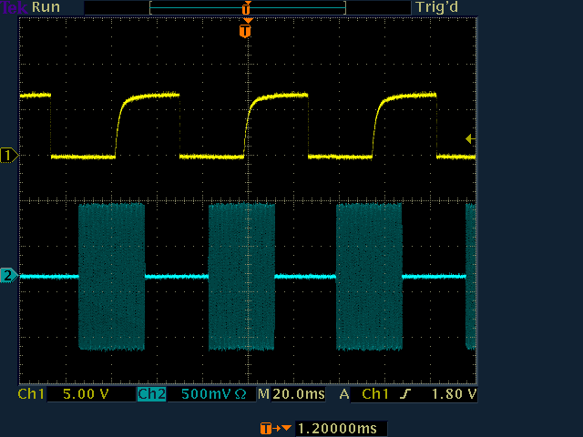
Figures 6 and 7 show the key input and the HermesLite2 keyed RF output when using the circuit of Figure 4 on Linux. Using the circuits in Figures 2 and 3 would show the same result. Visual inspection showed little jitter in the pulse timing. Performance was better than expected.
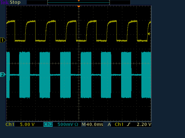
For the circuit of Figure 5 the MCU polls the keyer signal, reads its clock and sends 4-byte messages to the serial port. The messages consist of a time stamp, the key state and some error checking. This scheme depends on the PC not losing any serial port bytes, but does not depend on real time processing. The messages are sent to the transmitter as above. There is no additional thread to read the serial port; I am using the sound thread. Visual inspection showed no jitter. The MCU was also generating a sidetone at the time.
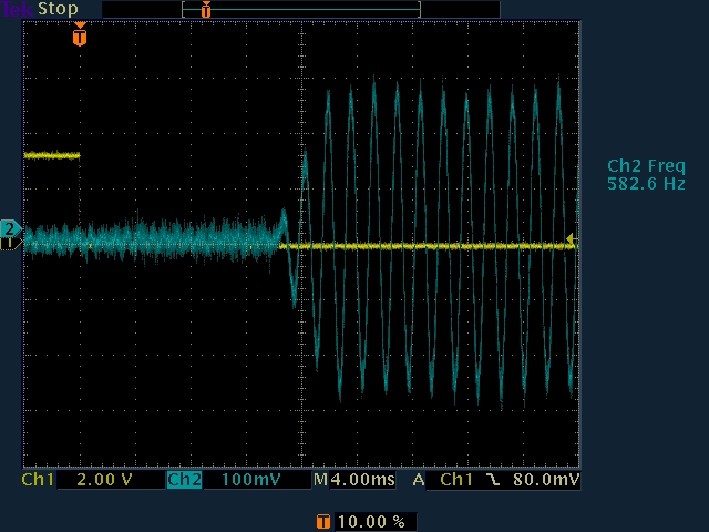
Figures 8 and 9 show the key input and the HermesLite2 keyed RF output when using the circuit of Figure 5 on Linux.
See updated results below.
Sidetone is an audible tone sounded while the key is down. An operator depends on this tone when sending CW, especially when using a "bug" or paddles. There must be no delay between key down/up and sidetone. This is difficult for a PC because it really does require real time processing. The sidetone generation in Quisk is much too slow to be useful. By ear, the circuit of Figure 5 had a perfect sidetone as expected. A normal keyed audio oscillator may not work because of startup time. A good solution is a free running oscillator keyed with an analog switch and used in the circuit of Figure 3. However, most keyers will have a builtin sidetone, and an additional sidetone may not be necessary.
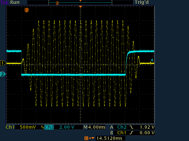
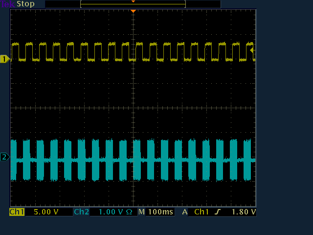
Figure 10 shows the key signal and the sidetone output from the circuit of Figure 5. The rise time was set to 4 milliseconds. The sidetone has zero delay. The waveform shows artifacts from the DDS clock. The sidetone could be low pass filtered, but it sounds good as is.
Alan Hopper, the author of Spark SDR, has published results showing excellent keying and sidetone using MIDI. A microcontroller such as an Arduino is connected to the PC using USB, and is programmed to be a MIDI device. The PC understands that MIDI is time sensitive and will endeavor to deliver the MIDI messages promptly. The key and potentially a wide variety of other peripherals are connected to the microcontroller, which generates MIDI messages for the events. There is no software synth in this scheme, and keying events and sidetone generation are handled by his Spark SDR software.
I have been working on speeding up the sound software in my Quisk program. No matter what the keying source, a sidetone with almost no delay requires fast access to the sound card. This work is almost complete. The new sound is much faster and I can now use it for my tests. Using a separate thread to poll the serial bits was a failure on Windows, so now I am just polling the bits with the main sound thread in Quisk.
I am using Quisk to measure the time between a key press and the time the sound voltage appears at the speaker terminal with my two-channel Tektronix TDS 3052C oscilloscope. For a reference I am using the Hermes-Lite2 with its internal key connector. This provides a key signal back to the PC using UDP packets. Internal delay within the HL2 is a few milliseconds, and the network delay should be small. I can compare this speed to the speed of the serial port CTS connection from the circuits above. For both cases, Quisk either reads the UDP key signal from the HL2 or polls the serial port CTS bit and then creates the sidetone. The two sound cards I am using are the Asus motherboard sound from my PC and a Behringer UCA222 USB-connected device. Quisk has a hardware poll timing adjustment, and I tested at 5 and 10 milliseconds. For Linux I am using ALSA drivers. For Windows I am using Wasapi.
For the reference case of a keyer directly connected to the HL2, and on a Linux PC with a 10 msec hardware poll, I get a delay of 22 to 28 msec on the USB sound card. The delay is not constant, so I stare at the 'scope for a while to get a range. The complete results are:
Key to HL2,  10 msec poll, Linux USB sound       22 to 28 msec
Key to  CTS, 10 msec poll, Linux USB sound       20 to 30 msec
Key to  CTS, 10 msec poll, Linux Internal sound  10 to 18 msec
Key to HL2,   5 msec poll, Linux USB sound       12 to 18 msec
Key to  CTS,  5 msec poll, Linux USB sound       12 to 18 msec
Key to  CTS,  5 msec poll, Linux internal sound   6 to 10 msec
Key to  CTS,  5 msec poll, Windows USB sound      8 to 14 msec
Key to  CTS,  5 msec poll, Windows internal sound 6 to 10 msec
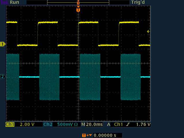
The main result is that the serial port CTS signal is comparable in speed to a direct key connection to the HL2, and is capable of high speed CW. It is also clear that sound latency can vary substantially between sound cards. The internal sound is nearly twice as fast as the USB sound. Figure 11 shows the key and speaker voltage for a 5 msec poll to the USB sound card.
I added a MIDI interface to Quisk and tested it with the circuit of Figure 5. The Arduino program is a simple MIDI emulator that sends Note On and Off messages. Using my USB sound card and a 5 msec hardware poll I measured the delay between key down and the sidetone.
Key to MIDI, 5 msec poll, Windows USB sound      8 to 13 msec
Key to MIDI, 5 msec poll, Linux USB sound       26 to 30 msec
The performance on Windows is excellent and similar to using CTS. Performance on Linux is somewhat slower than using CTS. This is the Arduino program I used:
/*
   This is a simple MIDI CW key source.

   Created: 8/14/2020
   Author: James C. Ahlstrom

   http://james.ahlstrom.name
*/

#include "MIDIUSB.h"

#define AUX_PIN    6
#define KEY_PIN    7
#define KEY_PITCH   57
#define VELOCITY    127
#define CHANNEL     0

byte key_down;

void setup() {
  pinMode (LED_BUILTIN, OUTPUT);
  pinMode (KEY_PIN, INPUT);
  pinMode (AUX_PIN, INPUT_PULLUP);
  key_down = 0;
}


void loop() {
  if (digitalRead(KEY_PIN)) {    // key is up
    if (key_down)
      noteOff(CHANNEL, KEY_PITCH, VELOCITY);
      digitalWrite(LED_BUILTIN, LOW);
      key_down = 0;
  }
  else {    // key is down
    if ( ! key_down) {
      noteOn(CHANNEL, KEY_PITCH, VELOCITY);
      digitalWrite(LED_BUILTIN, HIGH);
      key_down = 1;
    }
  }
}

// First parameter is the event type (0x09 = note on, 0x08 = note off).
// Second parameter is note-on/note-off, combined with the channel.
// Channel can be anything between 0-15. Typically reported to the user as 1-16.
// Third parameter is the note number.
// Fourth parameter is the velocity (64 = normal, 127 = fastest).

void noteOn(byte channel, byte pitch, byte velocity) {
  midiEventPacket_t noteOn = {0x09, 0x90 | channel, pitch, velocity};
  MidiUSB.sendMIDI(noteOn);
  MidiUSB.flush();
}

void noteOff(byte channel, byte pitch, byte velocity) {
  midiEventPacket_t noteOff = {0x08, 0x80 | channel, pitch, velocity};
  MidiUSB.sendMIDI(noteOff);
  MidiUSB.flush();
}
I don't see an advantage to using MIDI for keying instead of CTS. MIDI requires a microcontroller while CTS just uses a serial adapter. But MIDI has the advantage that there are inexpensive off-the-shelf MIDI devices, and some users have expressed an interest in using these to control Quisk. Now that Quisk has a MIDI interface, this should be easy. But it will create an additional command set. Quisk can already be controlled from Hamlib, XML-RPC and from the Flex ZZ command set. Using MIDI creates yet another incompatible language, and one that will depend on the MIDI controller used. As someone once said, the nice thing about standards is that there are so many.
Thanks for reading. I hope this work will prove useful to other experimenters.